|
Model
|
|
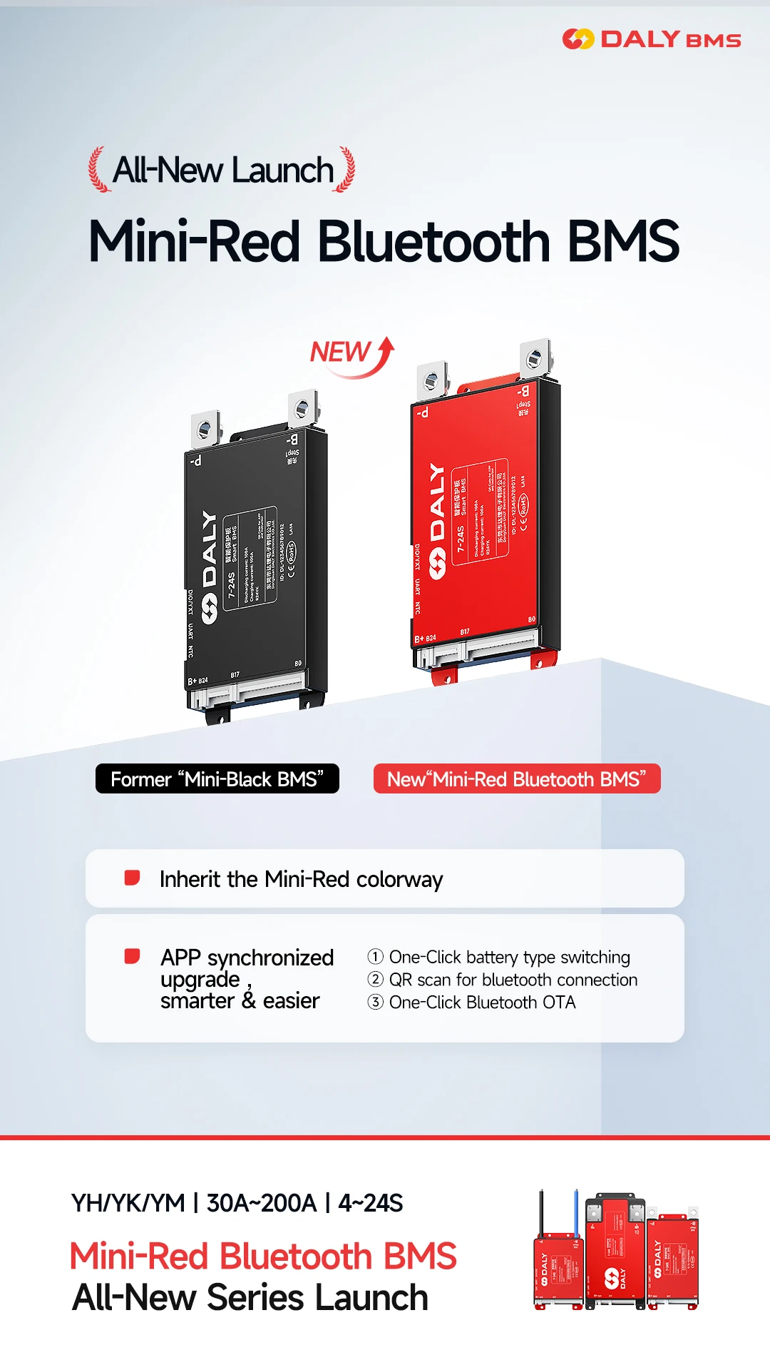
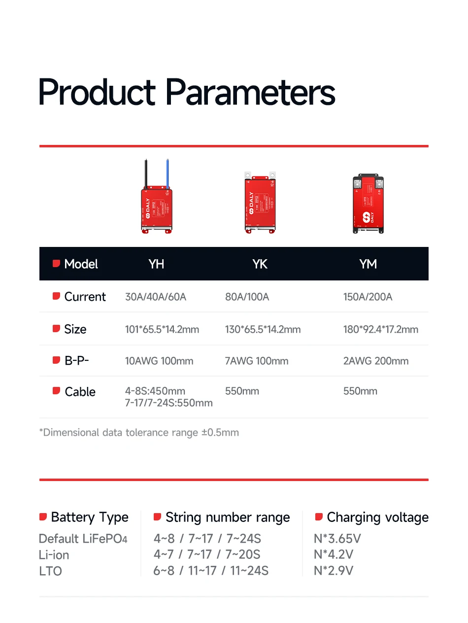
DALY SMART BMS: Y-series 30-60A(YH) 80-100A(YK) 150-200A(YM)
|
|
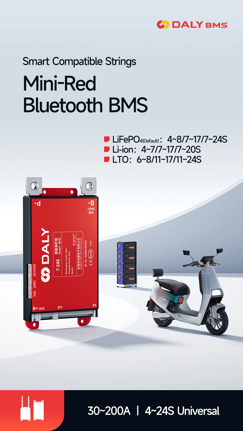
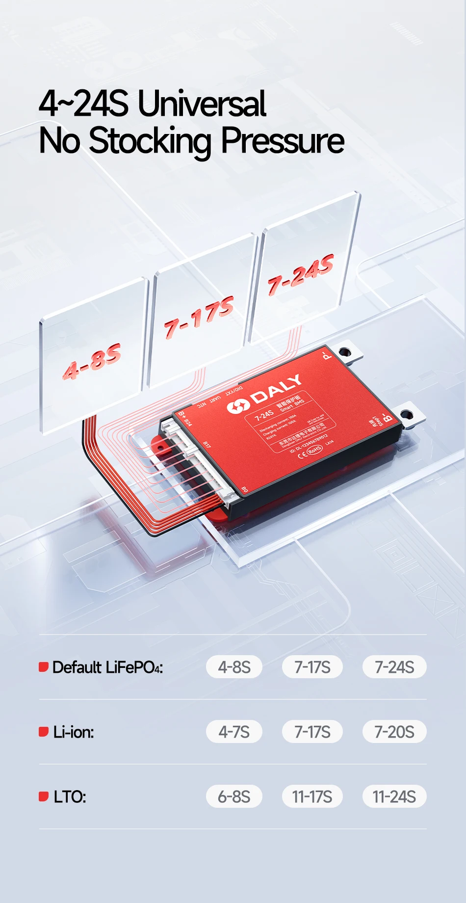
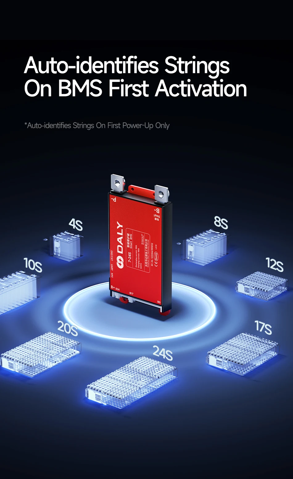
Optional strings range:4-8S 7-17S 7-24S
|
|
Optional current range:30A 40A 60A 80A 100A 150A 200A
|
|
|
|
|
|
Usage Scenario
|
|
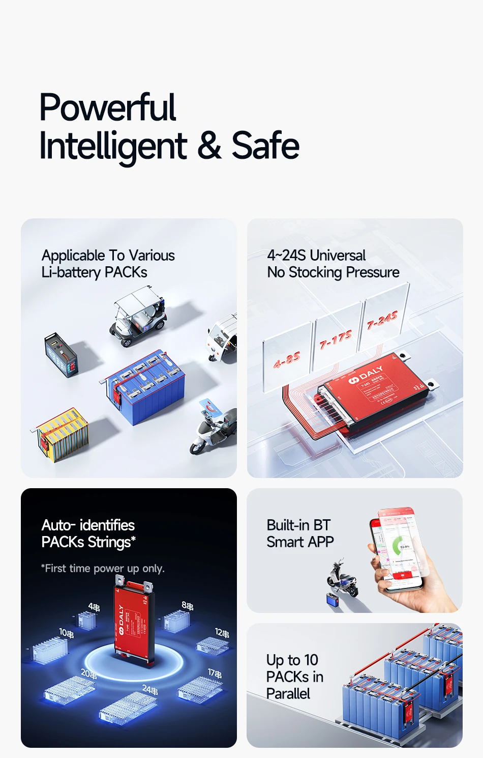
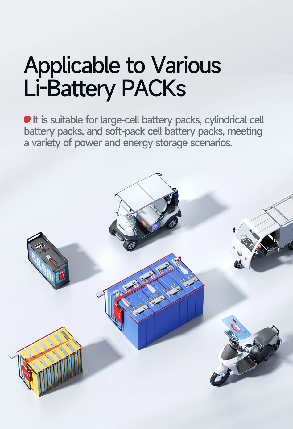
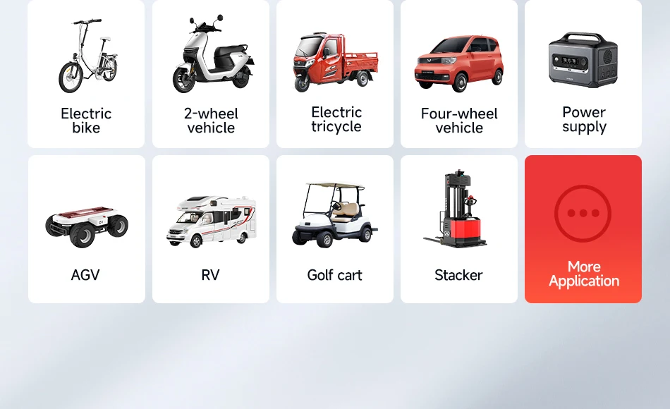
Used in RV energy storage,photovoltaic energy storage,home and outdoor energy storage,electric vehicles,tricycles,forklifts,tourist vehicles,golf cart etc.
|
|
|
|
|
|
Support Customization
|
|
Bulk orders can customize functions,parameters,logo.
|
|
Support OEM
|
|
Standard BMS, smart BMS all can be customized
|
|
For details, please contact customer service
|
|
|
|
|
|
|
|
How to choose the right BMS
|
|
Attention
|
Illustration
|
Mismatched BMS Consequences
|
|
Lithium
|
BMS type and lithium battery type must be in
|
1、BMS damaged,even bms and battery burn out
|
|
battery type
|
one-to-one correspondence(Li-ion/Lifepo4)
|
2、The battery cannot be fully charged and discharged
|
|
|
|
|
|
Number of battery pack
|
BMS strings and battery strings must be in
|
BMS and battery burn out
|
|
strings
|
one-to-one correspondence
|
|
|
|
|
Selection method
|
load maximum power÷(string number of battery×overdischarge voltage)×coefficient
|
|
in experience
|
Depending on the battery usage scenario, the coefficient value is also different
|
|
|
Please consult customer service for specific values
|
|
|
|
Specialty
|
|
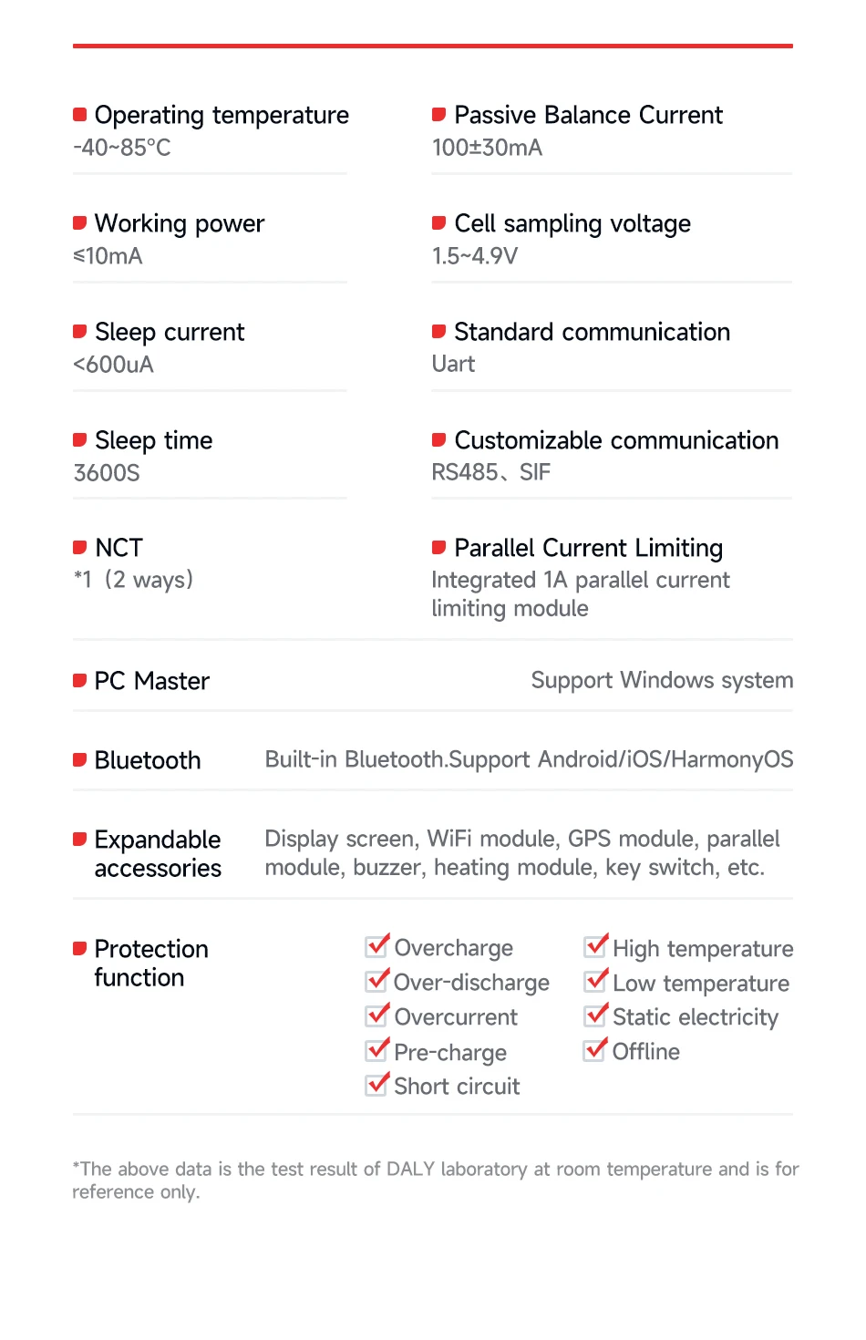
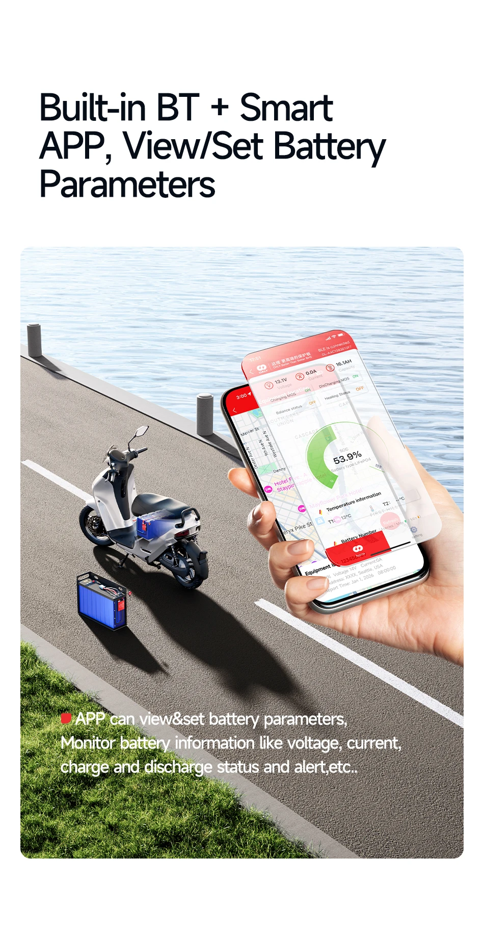
Bluetooth function:You can monitor battery data in real time by connecting to the APP
BMS built-in Bluetooth
|
|
|
|
Superiority
|
|
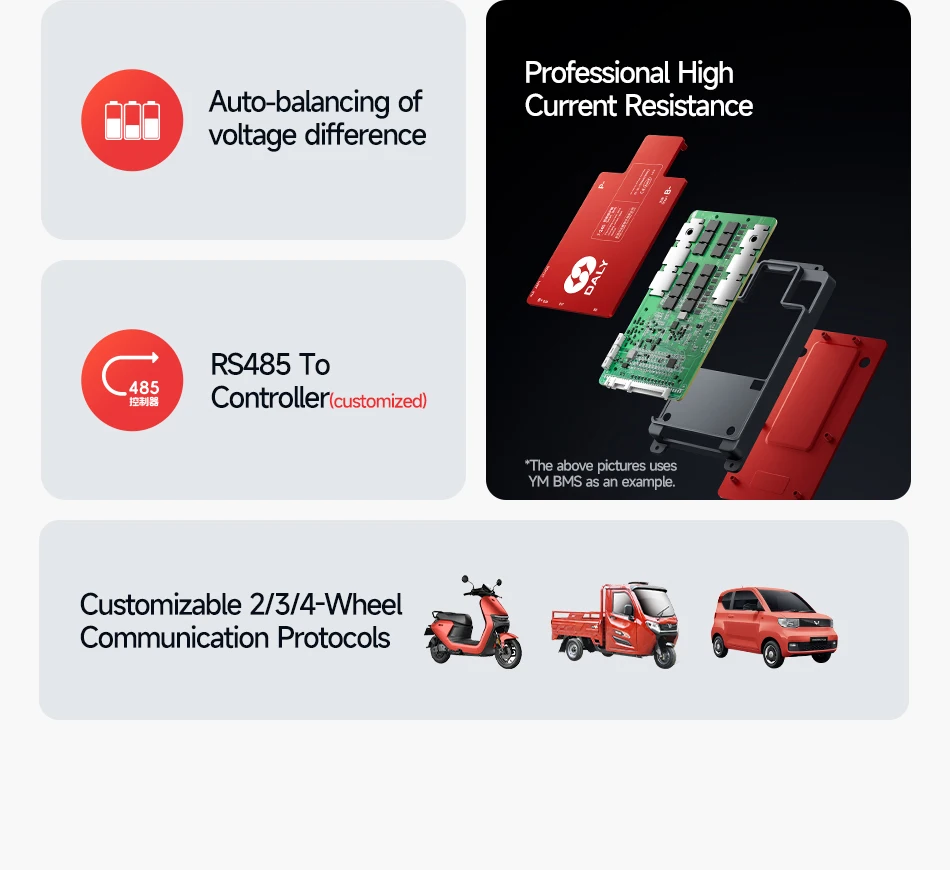
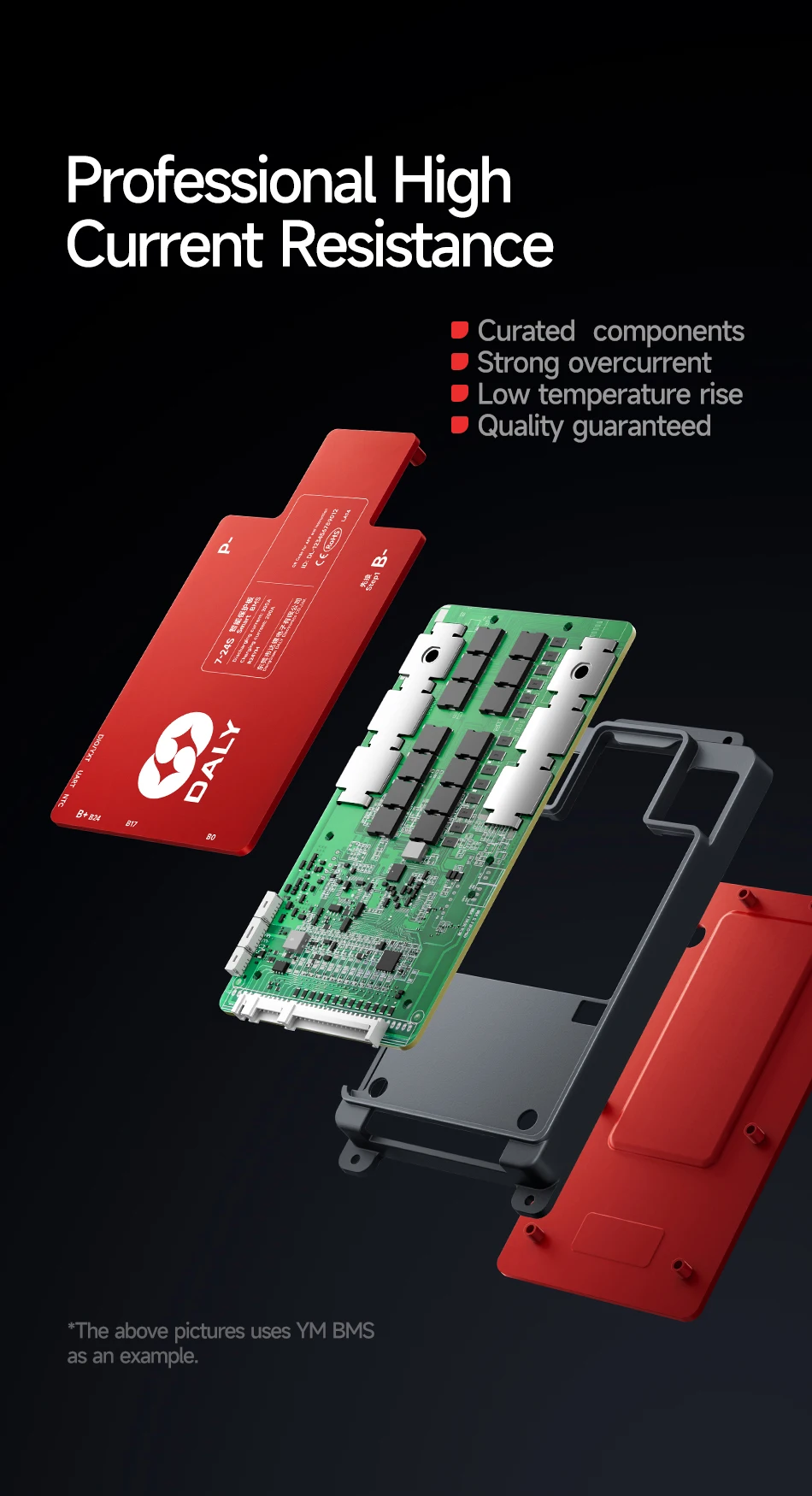
1、High-quality microelectronic components:precise and fast IC.Low resistance,high withstand voltage MOSFET.
|
|
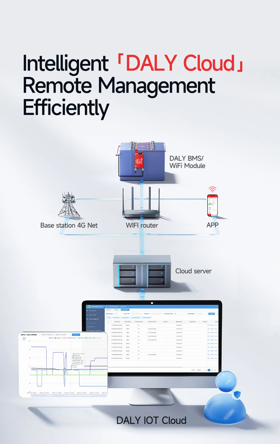
2、Through the Bluetooth APP, the battery data is constantly monitored.
|
|
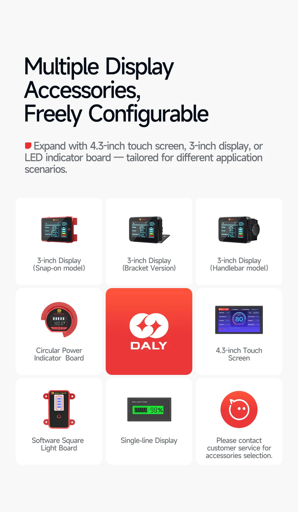
3、A variety of accessories,can easily control the data and modify the parameters.
|
|
4、A variety of communication modes,data monitoring,alarm backtracking,data reading, and upgrade can be easily realized
|
|
5、Thermal silica,accelerate the heat dissipation.Ensure the smooth operation of the battery.
|
|
6、Preset interface,buckle cable,make the connection more convenient.
|
|
|
|
Basic Functions
|
|
Over-charging protection
|
Over-discharging protection
|
|
Over-current protection
|
Temperature protection
|
|
Disconnect protection
|
Short Circuit Protection
|
|
Balance Function
|
Short Circuit protection recover
|
|
|
|
Package Contains
|
|
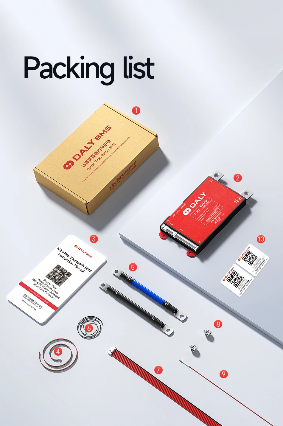
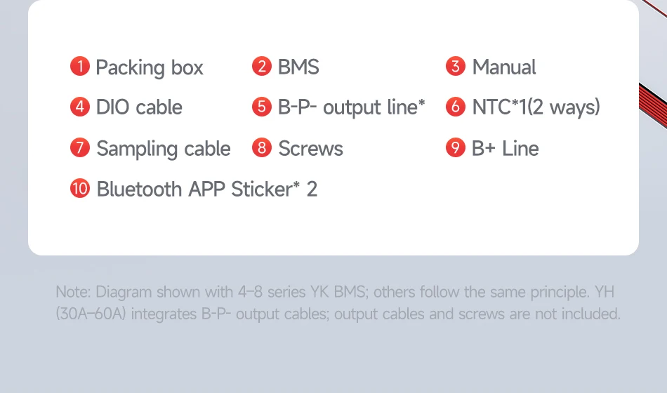
BMS*1pcs
|
Sampling cable*1pcs
|
Temperature probe(NTC)*1pcs
|
|
B+ cable *1pcs
|
English manual *1pcs
|
|
|
|
|
Optional accessories
|
|
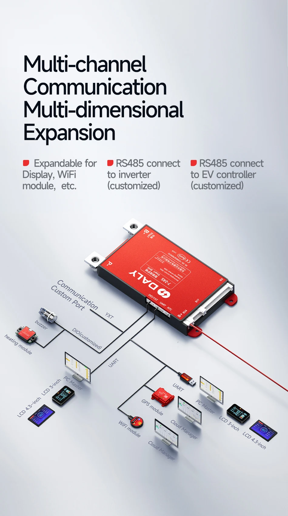
UART to USB cable
|
Battery Capacity Indicator
|
Touch screen LCD
|
|
|
|
Customization
|
|
soft switch
|
RS485 and CAN Communication
|
|
key switch
|
DO/I port for special needs
|
|
Optional accessories, customized accessories must match the BMS model and be purchased at the same time.
|
|
please contact customer service for details
|
|
|
|
|
|
|
|
|
|
|
|
|
|
|
Balance cable connection
|
|
|
Find the total positive and total negative of the battery pack.
|
|
Find B-/P- of BMS
|
|
Insert temperature probe (NTC) into the BMS
|
|
|
Note: When soldering, the balance cable cannot be inserted into the BMS
|
|
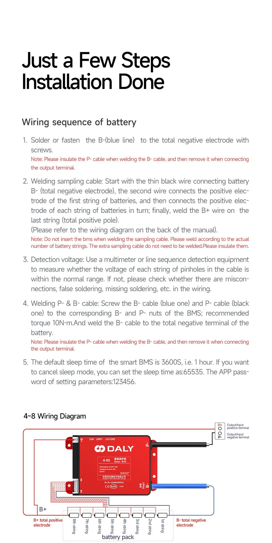
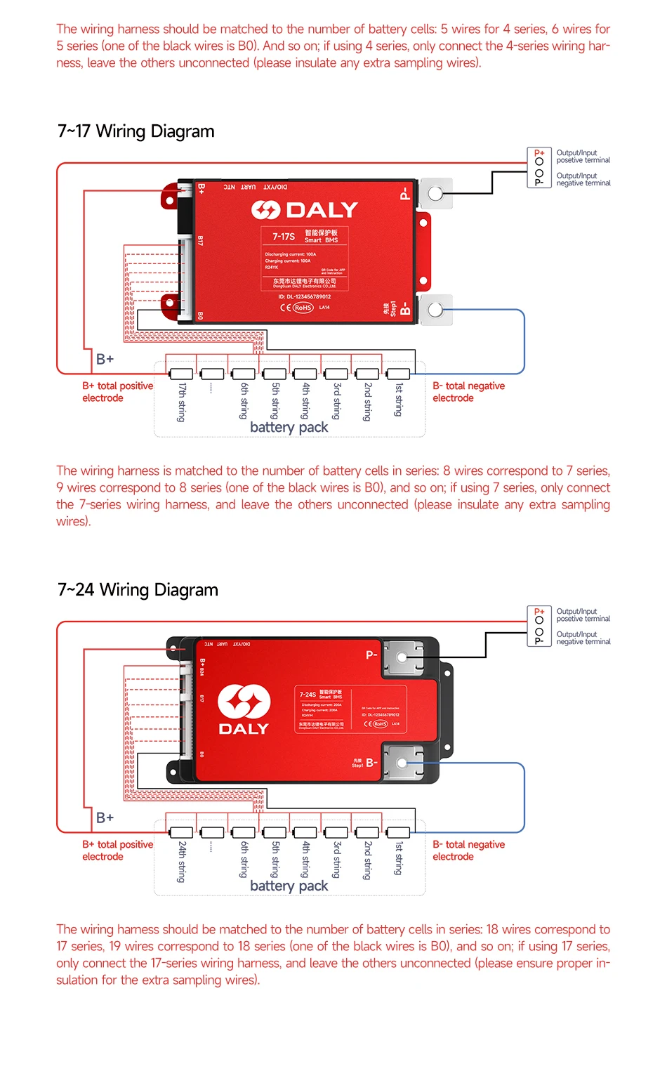
(1)Weld Sampling cables: Start from thin black wire to B- (total negative),then connect each cell's positive in order. Last red wire to B+ (total positive)
*Note: Do NOT plug into BMS during welding. Insulate unused wires.
|
|
(2)Check voltages: Use multimeter or wire tester to confirm each cell'svoltage is normal. Fix any miswiring or poor soldering.
|
|
(3) Weld output wires: Secure B- and P- to BMS with 10N·m torque; weld B-to battery negative.
*Note: Insulate P- before final connection.
|
|
(4) Plug NTC and Sampling cable: Insert NTC, then plug sampling cable toauto-activate BMS.
|
|
|
|
|
Measure whether the battery voltage(B+→B-)is consistent with the output voltage of the BMS(B+ P-).
|
|
If the two voltage values are equal, it means that the BMS is working normally.
|
|
|
|
|
|
|
|
|
|
|
|
|
|
|
|
|
Passive Equalization
|
|
|
3.4V
|
|
|
≥20mV
|
|
|
100±30mV
|
|
|
|
1.Reach the set balanced start voltage
|
|
2.The highest voltage reaches the set balanced start voltage difference.
|